DC Motor
Project overview
A small team’s brief: design, simulate, build, and test a permanent magnet brushed DC motor from raw materials, scaled as a prototype for a small conveyor-belt drive, under hard constraints (a rotational speed limit, a current limit, and a ban on commercial carbon or graphite brushes, so even the brushes had to be designed and built from scratch). My own contribution centred on the analytical and MATLAB side, optimising the wire gauge, turns count, and supply voltage, and developing the transient simulation used to predict the motor’s behaviour before anything was built. The rest of the team led the physical construction and assembly. This project is complete: built, tested, and assessed.
Selected engineering challenges and decisions
Choosing the wire gauge and operating point. Wire gauge is a direct trade-off: thinner wire allows more turns in a fixed slot area, more flux linkage and torque, but adds resistance and copper losses, while thicker wire does the opposite. Rather than guess at it, I wrote a MATLAB script to sweep that trade-off properly, and a second script to find the supply voltage that made the best use of the motor’s available current limit during startup. This mattered because the same trade-off, done by hand, is easy to get wrong in either direction, under-using the current limit or overheating the windings.
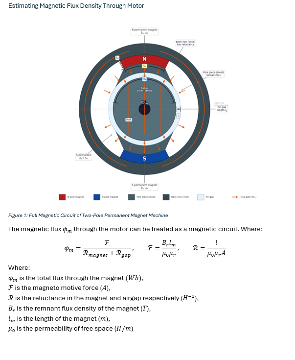
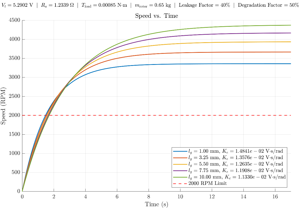
The full transient simulation (current, torque, back-EMF, angular acceleration, speed, and power, via an adaptive ODE solver) was swept across a range of air gap lengths, since the air gap directly affects the motor constant and how stiff or fast the resulting machine would be, to choose a practical operating point against the speed limit.
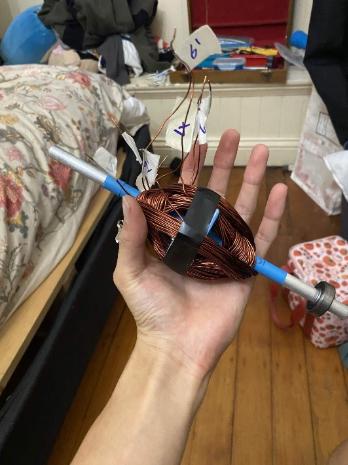
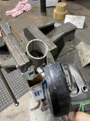
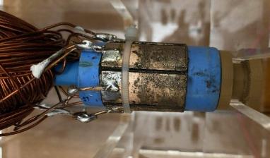
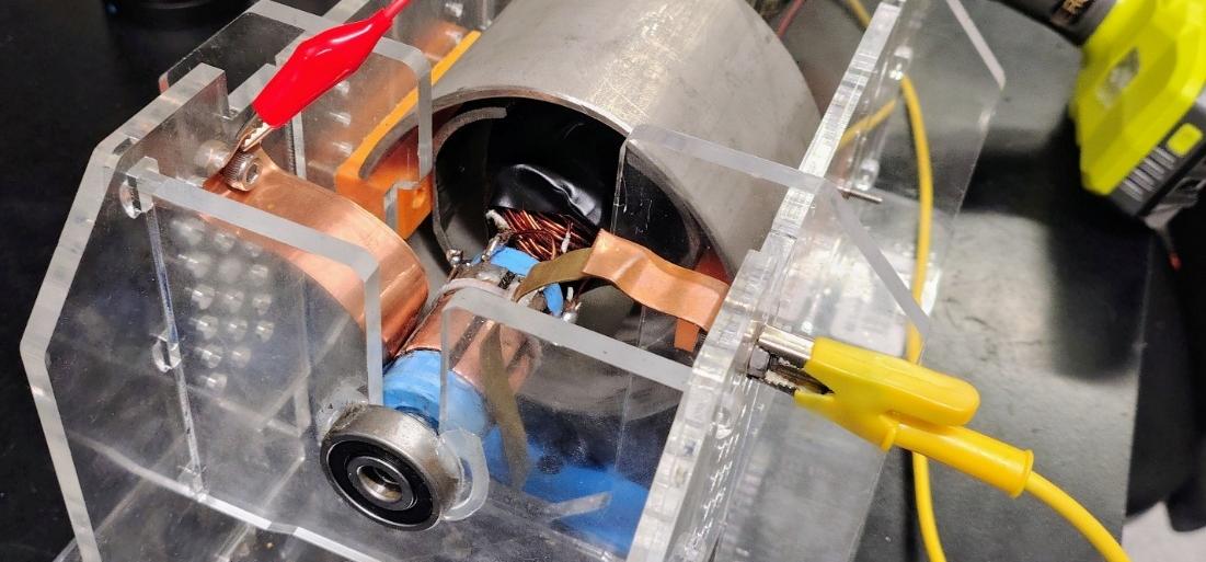
Custom brushes and commutator under a no-commercial-parts constraint. With commercial carbon or graphite brushes banned by the brief, the contact surfaces had to be designed from scratch, and the commutator went through four iterations: a PVC and 3D-printed hybrid, then a fully 3D-printed version, both of which suffered thermal wear and deformation under the heat generated by brush friction, before a final design using a PVC body, a press-fitted wooden insert, and copper pipe segments as the actual contact surfaces. The brushes themselves started as brass plates soldered to copper pipe supports, later refined to graphite rods for better contact and lower friction. This mattered because the brush-commutator interface turned out to be the dominant real-world loss in the finished motor (below), so its reliability under sustained friction and heat was never a minor detail.
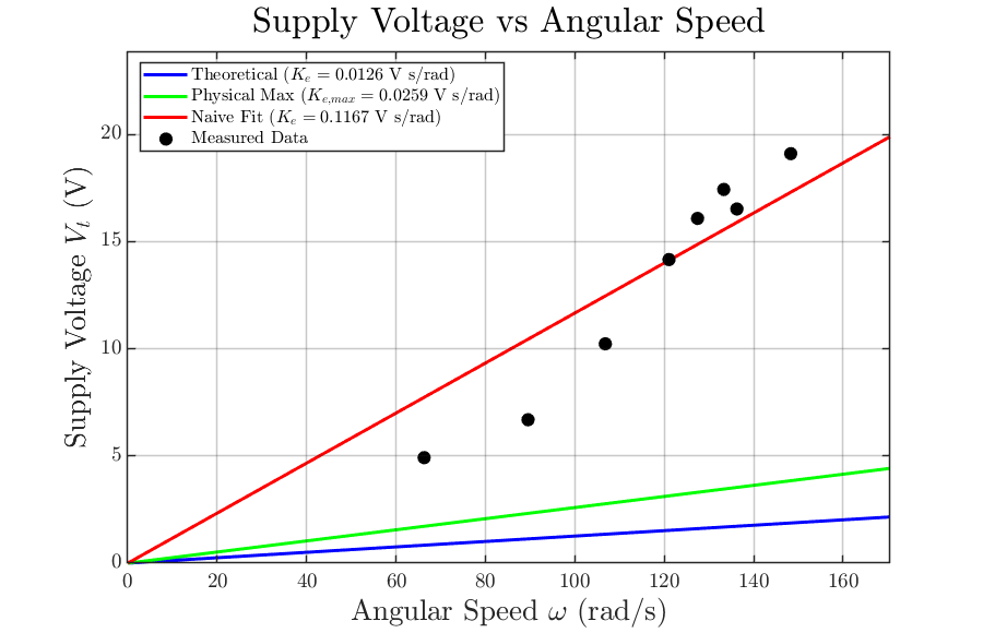
Verification or evidence
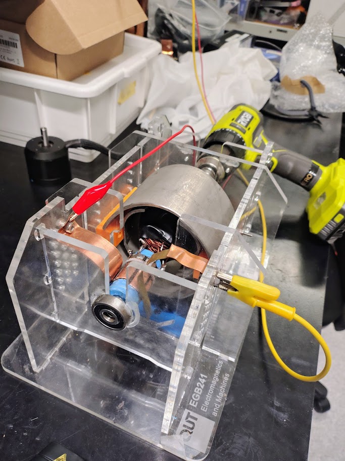
With the motor built, a drill clamped to the output shaft spun it as a generator, measuring voltage and speed at several points to back out the motor’s real electromagnetic constant, the same way the simulation had predicted it in theory.
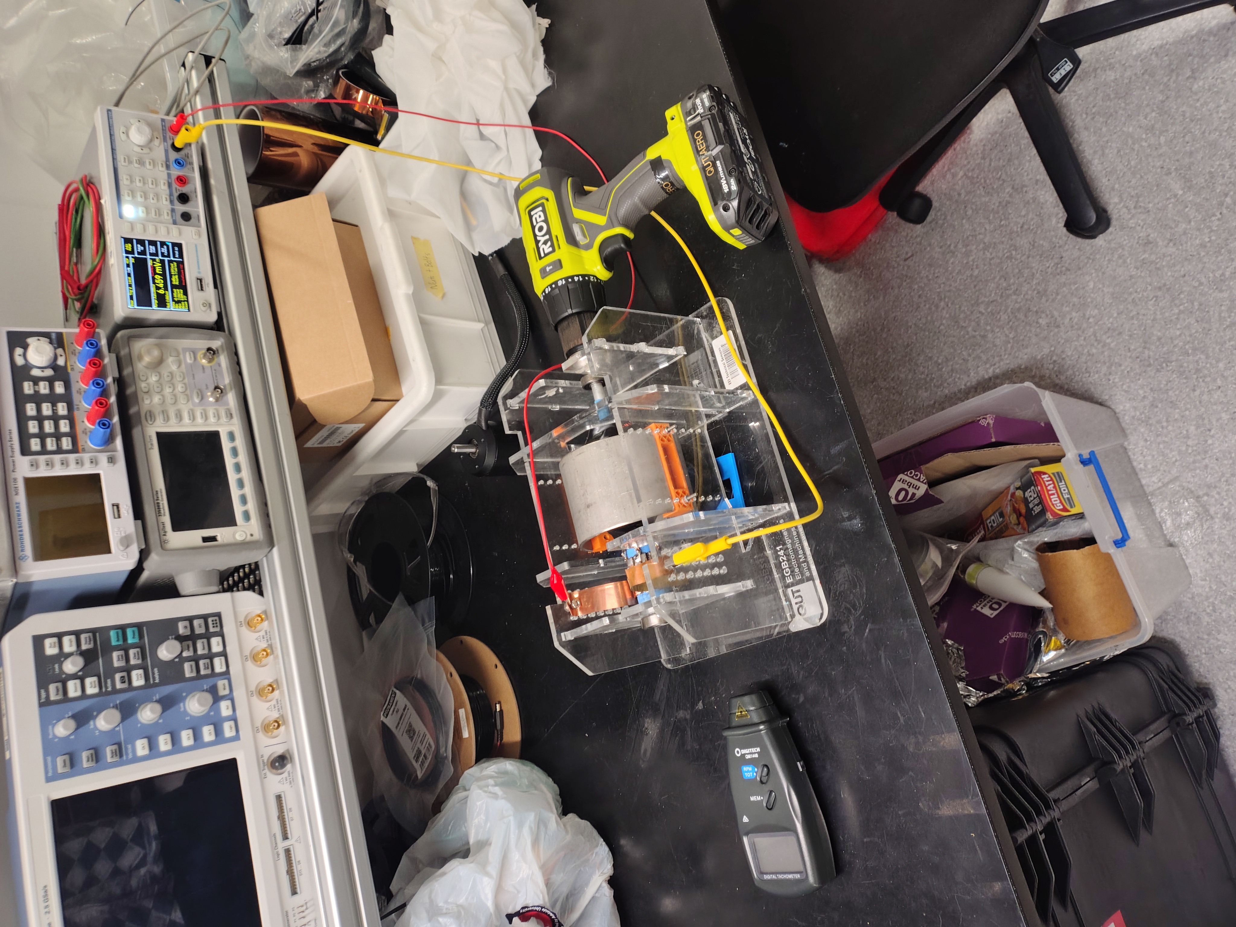
The measured data told a clearer story than the original analytical model: the magnetic circuit performed close to its physical maximum, far stronger coupling than the original model (which assumed significant flux leakage) had predicted, while the effective armature resistance rose from a theoretical 0.23Ω to a measured 1.3 to 3.7Ω depending on load, with visible arcing and several volts dropped across the brushes alone.
Current status
Completed: the built motor reached about 1400 RPM at 19V and 4.3A unloaded, with the full set of design, simulation, build, and test results above. This was a closed university assessment; no further development is planned.
What I learned or am proud of
The most interesting result wasn’t where the team expected it. We’d focused heavily on the magnetic circuit, and it turned out to perform near its physical limit, but the dominant real-world loss came from the brush-commutator interface, a part of the design the original analytical model had under-weighted, pushing peak measured efficiency down to under 1%. The lesson I took from it: an analytical model is only as good as where you choose to spend your modelling effort, and measured data is what actually tells you whether you spent it in the right place.
Gallery