Digital LQR Maglev Controller
Project overview
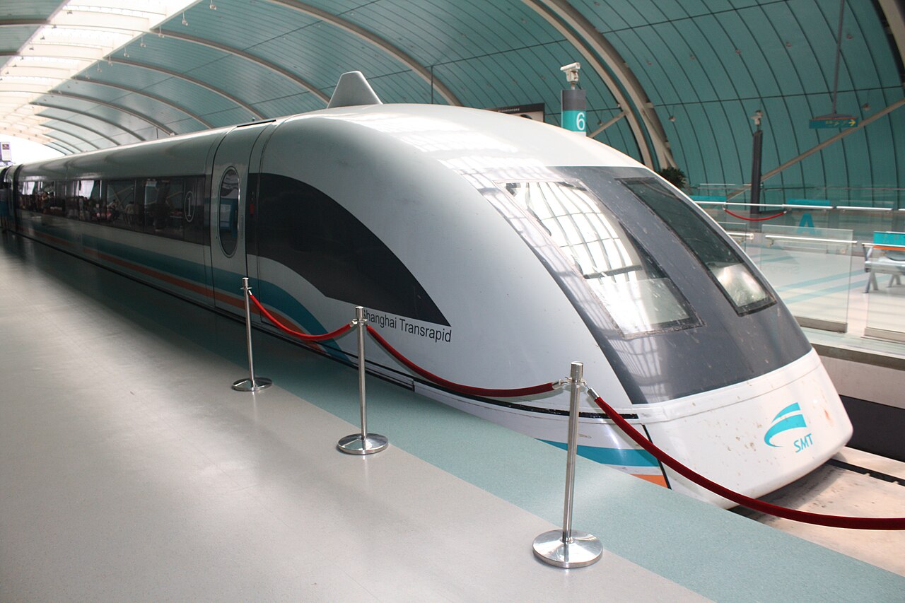
Design a digital control system to hold a magnetic levitation (maglev) module at a stable height. The system is open-loop unstable and strongly nonlinear, it has to be actively controlled at all times to stop the levitating carriage from dropping onto the track, under a brief calling for a fast settling time with very little overshoot, since a real carriage that overshoots risks striking the track. The design is complete and validated.
System architecture
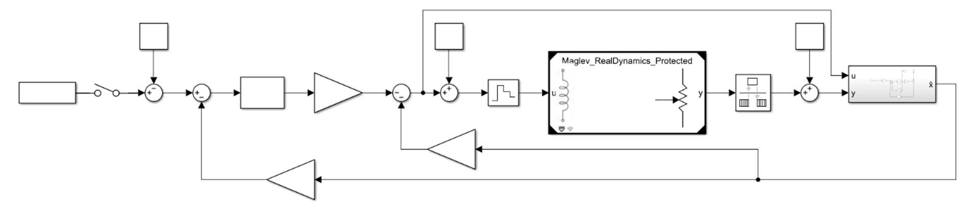
A discrete-time full-state feedback controller with integral action sits at the centre of the design, meeting the settling-time and overshoot spec. Since the real system can only measure position, a Kalman filter observer is layered on top to estimate the remaining states (velocity and coil current) from that single measurement. The full design was validated in Simulink against a realistic nonlinear plant model, with sensor noise, process noise, and disturbances included, not just the simplified linear model used for the design itself.
Selected engineering challenges and decisions
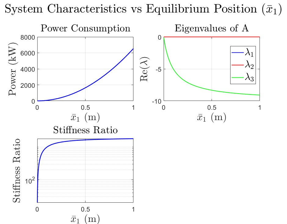
Choosing where to linearise a strongly nonlinear system. Rather than picking a linearisation point arbitrarily, I modelled the system’s nonlinear dynamics from first principles and swept the operating range to see how the power needed to hold the carriage up, and how stiff the dynamics become, both change with height. This mattered because the wrong linearisation point produces a controller that’s only valid in a narrow band around it, and the sweep is what turned that choice into an informed trade-off rather than a guess.
Estimating states that can’t be measured directly. The real system only measures position, but full-state feedback needs velocity and coil current too. A Kalman filter observer estimates both from the single position measurement, rather than assuming they’re available or adding sensors the real hardware doesn’t have. This mattered because a control design that assumes measurements you don’t actually have isn’t implementable, the observer is what makes the full-state feedback approach viable on the real instrumentation.
Verification or evidence
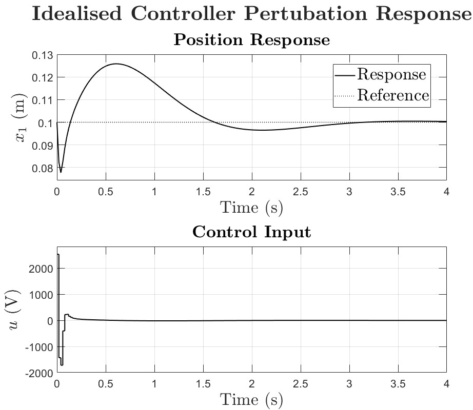
The controller settled in under two seconds with about 2% overshoot, comfortably inside spec.
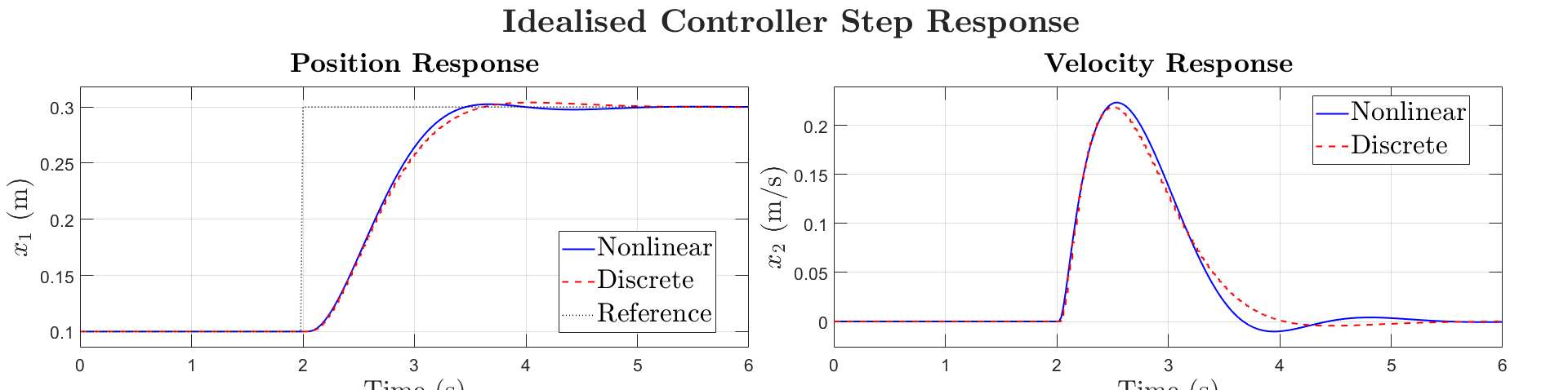
It also tracked reference heights well beyond the nominal operating point before the nonlinearity broke down the linear model’s validity, and rejected a large disturbance impulse (equivalent to a sudden 10kN force on the carriage) without ever letting it contact the track:
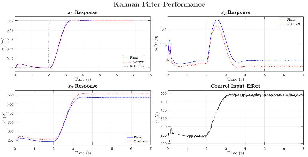
The observer tracked the true system states closely even with realistic sensor and process noise present, confirming the design was viable for an embedded implementation running at 50Hz.
Current status
Completed: the design meets every spec (settling time, overshoot, disturbance rejection, observer accuracy) under conditions more demanding than the linear design model assumes. This was a closed university assessment; no further development is planned.
What I learned or am proud of
The part I’d repeat on any control design is testing well past the assumptions the design itself relies on: a controller designed on a linearised model is only proven once it’s been run against the full nonlinear plant, with noise, with disturbances, and with reference steps larger than the design point. A design that only works under its own idealised assumptions hasn’t actually been validated yet, it’s just been calculated.