Super Heterodyne Receiver
Project overview
A small team’s task: design a super-heterodyne RF receiver covering 3 to 5GHz against a client-style specification, defined channel bandwidth, image and spurious signal rejection, sensitivity, and signal-to-noise ratio. My own focus was the conceptual design and the MATLAB analysis underpinning it: choosing the intermediate frequency and modelling the spurious products a real mixer produces. This is a conceptual, analytical design, never physically built, the deliverable is a verified design on paper, not hardware.
System architecture
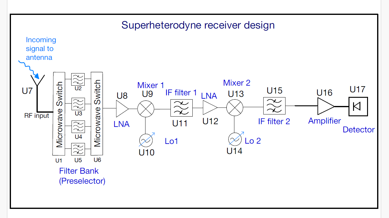
The design uses a two-stage down-conversion architecture, mixing the incoming signal down to an intermediate frequency in two steps to balance image rejection against selectivity. The full 3 to 5GHz band is split into four channels, each with its own preselection filter switched in ahead of the first mixer.
Selected engineering challenges and decisions
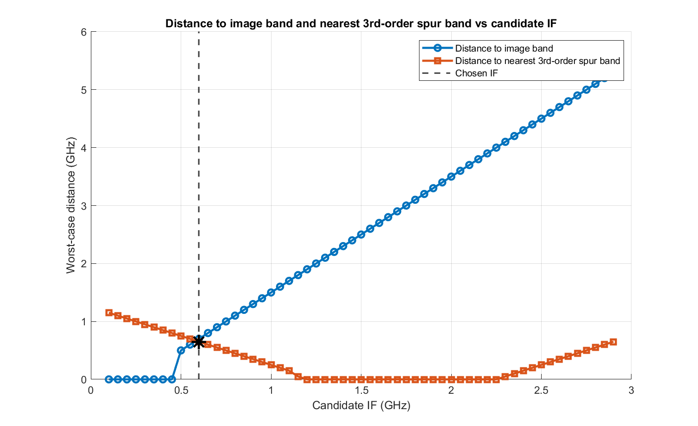
Searching for the intermediate frequency instead of eyeballing it. Before any components could be chosen, the design needed an IF that kept the system’s two biggest threats, the image band and third-order mixer spurs, as far away as possible. I wrote a MATLAB script that swept a wide range of candidate IFs and, for each one, calculated the distance to the image band and to the nearest third-order spur band, across every channel. This turned IF selection into a proper search rather than a frequency plan picked by intuition: the script chose the candidate that maximised the worst-case distance on both fronts simultaneously, which drove the final IF used throughout the rest of the design.
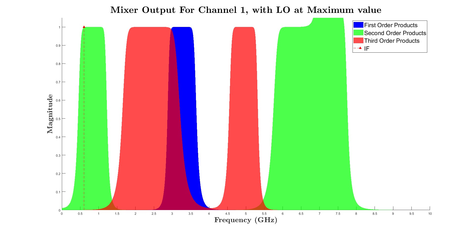
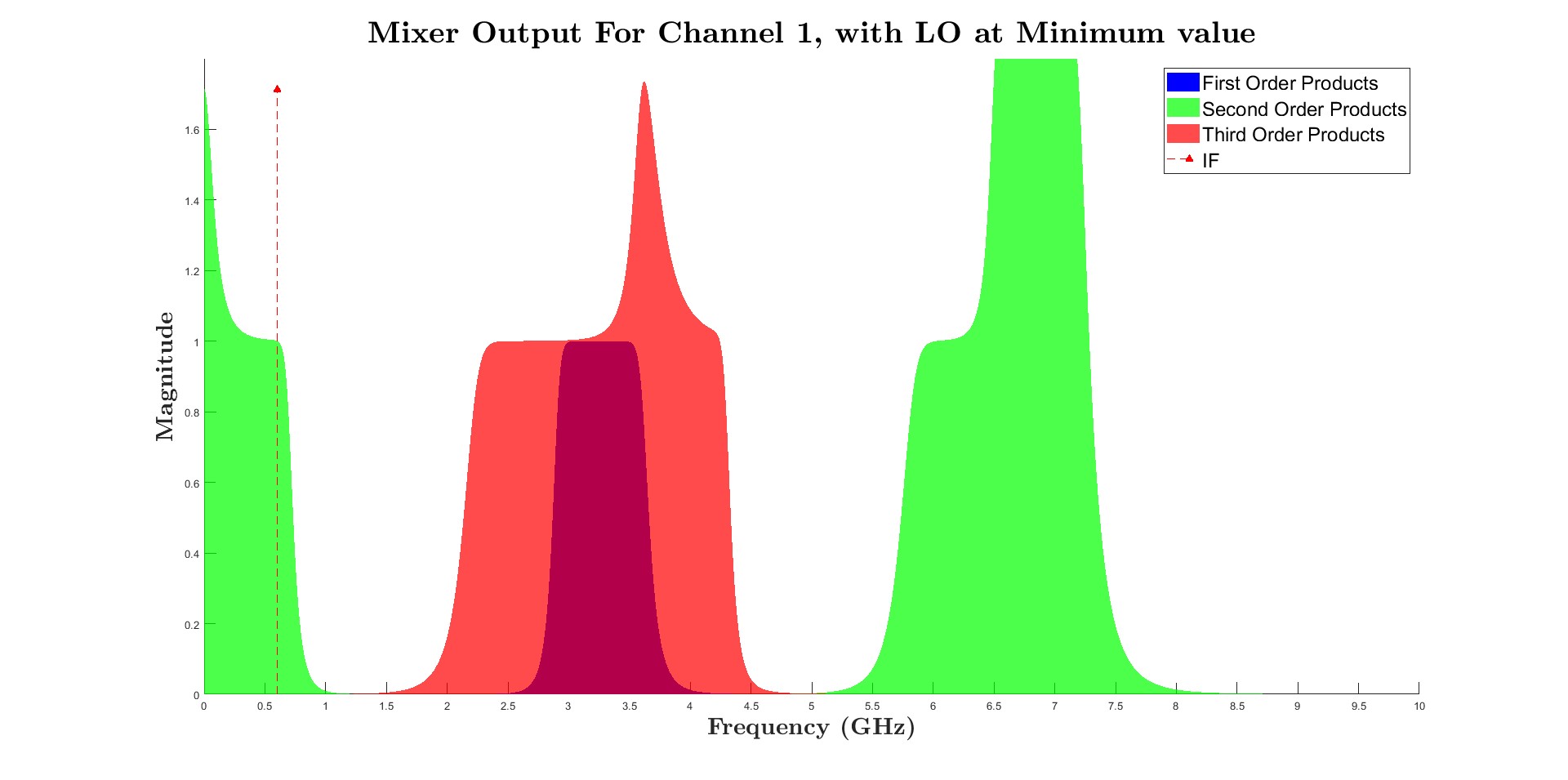
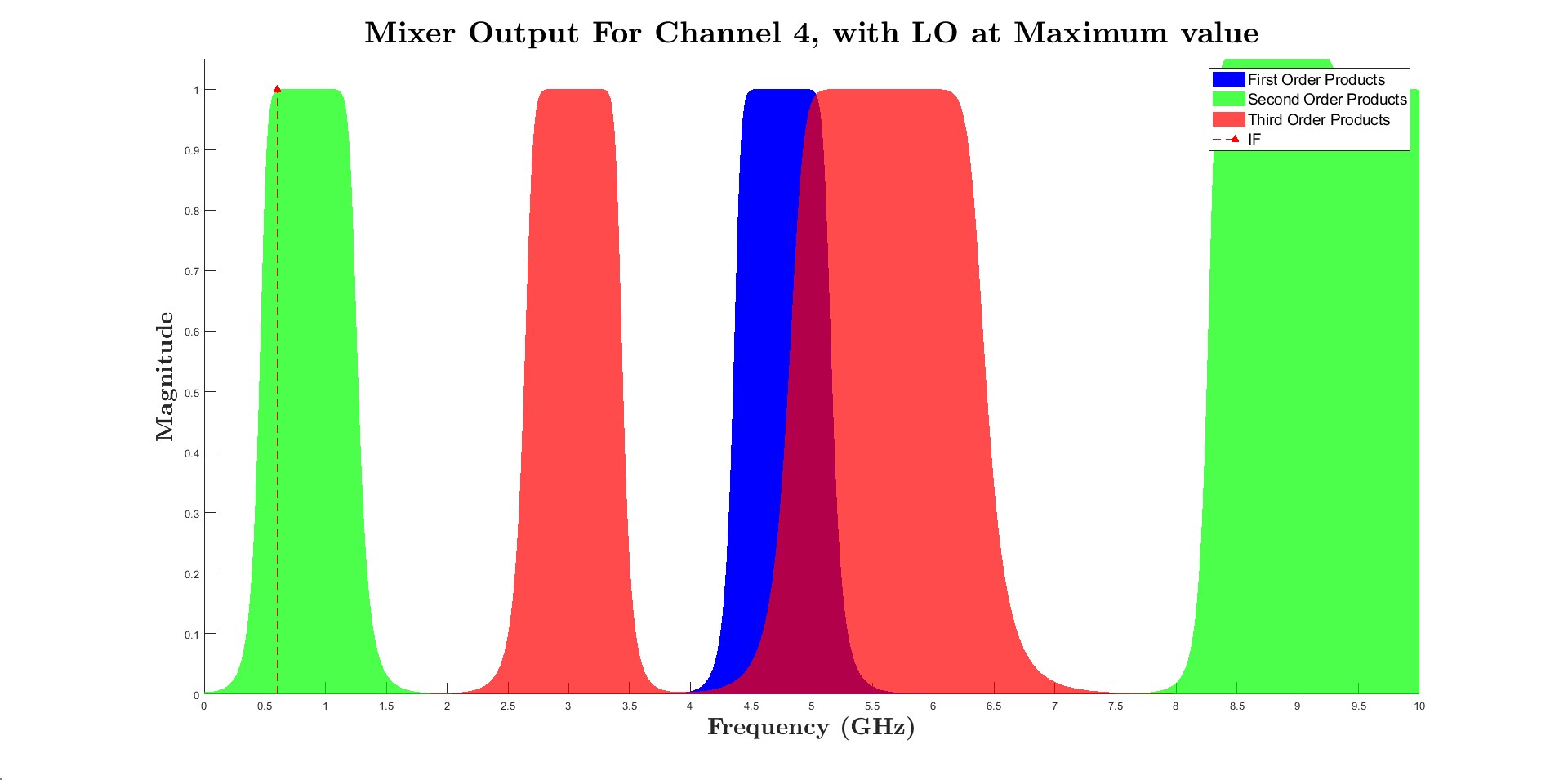
Modelling what a real, non-ideal mixer actually produces. A real mixer isn’t a perfect multiplier, it produces a forest of unwanted intermodulation products alongside the wanted signal. I wrote a function modelling a mixer’s first, second, and third-order products given an amplifier’s output spectrum and a local oscillator frequency, then ran it for the local oscillator at both ends of its tuning range, on every channel, to confirm no spur could ever drift onto the IF. This mattered because a receiver design that only checks the ideal down-conversion and ignores what a real mixer also produces hasn’t actually been verified against the failure mode that matters most.
Protecting the dynamic range without sacrificing sensitivity. The detector, not any of the amplifiers or mixers, turned out to be the limiting factor at the high-power end, all the gain stages had far more headroom before reaching their own compression points. Rather than attenuating the signal at the front end, which would cost sensitivity for weak signals, an attenuator sits late in the chain, just ahead of the final amplification stage, controlled by an automatic gain control loop that only engages once the signal crosses a threshold. This mattered because it stretches the usable dynamic range at both ends at once, instead of trading one extreme for the other.
Verification or evidence
The spurious-response analysis confirms unwanted mixer products stay clear of the intermediate frequency at both ends of the local oscillator tuning range, on the lowest channel:
The same held across the other three channels right up to the top of the band:
Current status
Completed (analytically): the verified design met every target in the specification, a minimum discernible signal of -98dBm, output SNR well above the 3dB demodulator requirement across the full input power range, and a dynamic range of close to 40dB. This was a closed university assessment and a conceptual design exercise; it was never built, and no further development is planned.
What I learned or am proud of
The habit I’d take from this project is turning a judgement call into a search wherever the parameter space allows it. IF selection is normally a frequency plan picked by intuition and experience; sweeping candidates and scoring each one against the actual failure modes (the image band, the spur bands) turned a subjective choice into a defensible, repeatable one.