Two-Tone Alarm Circuit
Project overview
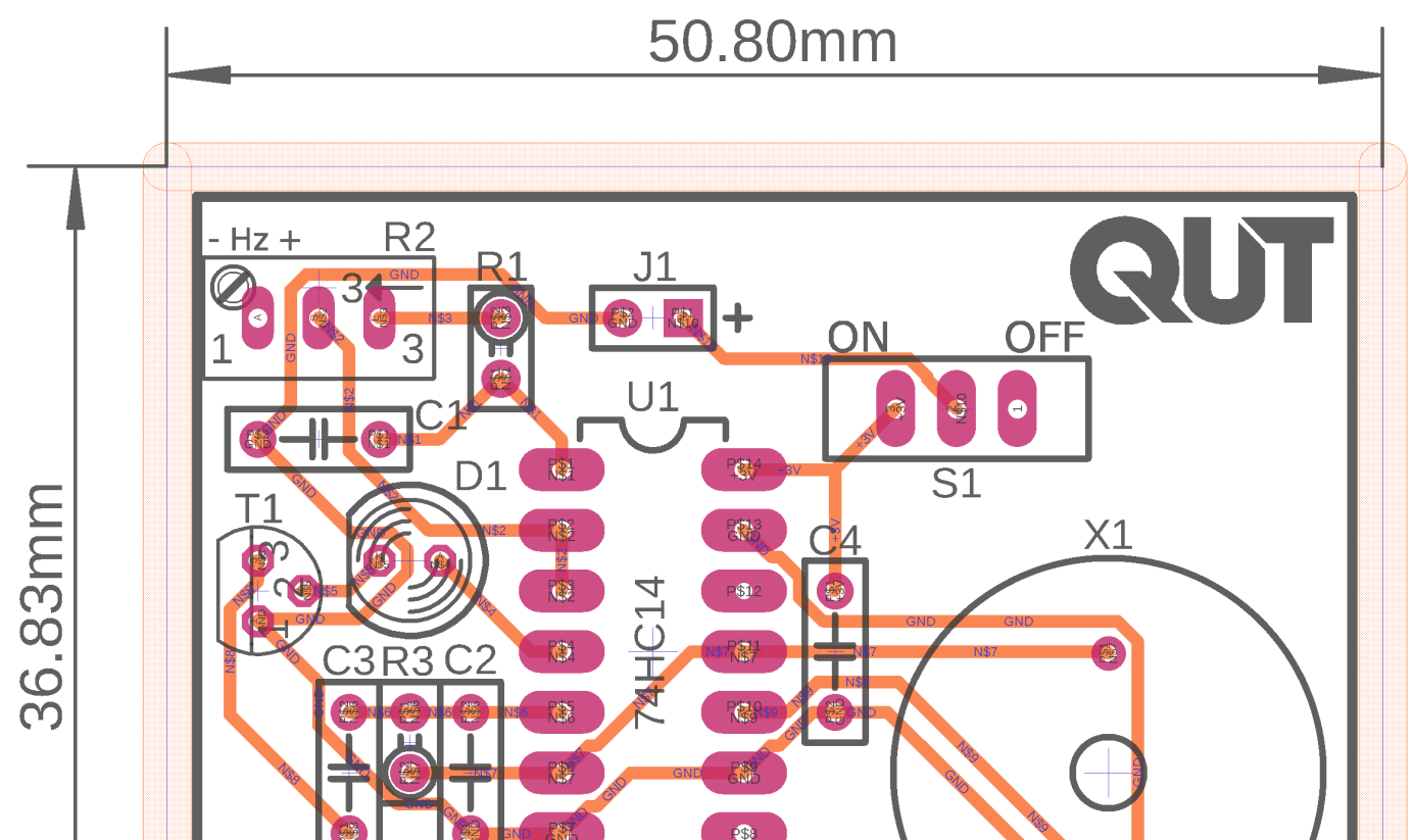
An individual assignment: design, simulate, and build a battery-powered alarm circuit that produces two distinct audible tones with a flashing LED, meeting a tight power budget and bill-of-materials cost target, manufacturable on a PCB. The project is complete: simulated, built, and verified on real hardware.
System architecture
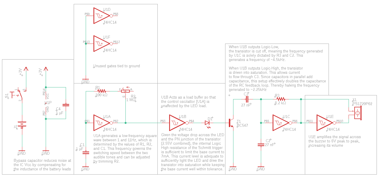
The circuit is built around a hex Schmitt trigger IC configured as a pair of relaxation oscillators: one slow oscillator controls how often the tone switches, and a transistor switches an extra capacitor in and out of the second oscillator’s feedback loop to flip between the two audible frequencies.
Selected engineering challenges and decisions
Designing around where the datasheet model breaks down. Component values were calculated from the datasheet’s oscillator equations, then refined through LTspice simulation and bench testing, because the real IC behaviour didn’t perfectly match the simplified datasheet model, its oscillator constant assumes a fixed supply voltage that doesn’t quite hold at the circuit’s actual 3V supply. This mattered because a design that trusts a simplified datasheet equation at face value, without checking it against simulation and a real bench measurement, can end up with the wrong oscillator frequencies on the actual hardware.
Getting a free current-limiting resistor out of the LED. The alarm’s LED doubles as both the visual indicator and the current-limiting element for the switching transistor’s base, removing the need for an extra resistor. Under a tight bill-of-materials and PCB-size budget, every component removed without losing function is a real win, not just a minor simplification.
Verification or evidence
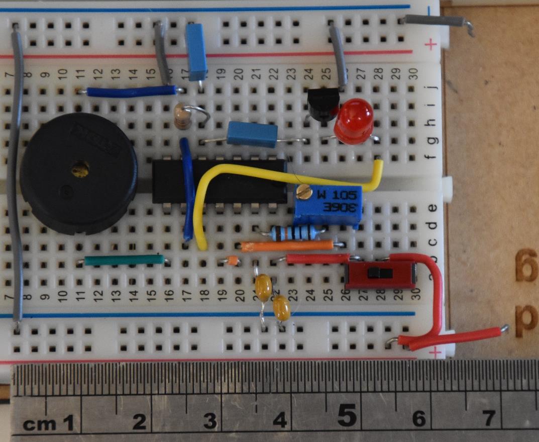
The design was simulated in LTspice, then built and verified on a breadboard with an oscilloscope, checking the control oscillator frequency, the tone-switching transition, and the LED/transistor bias point all matched what was simulated.
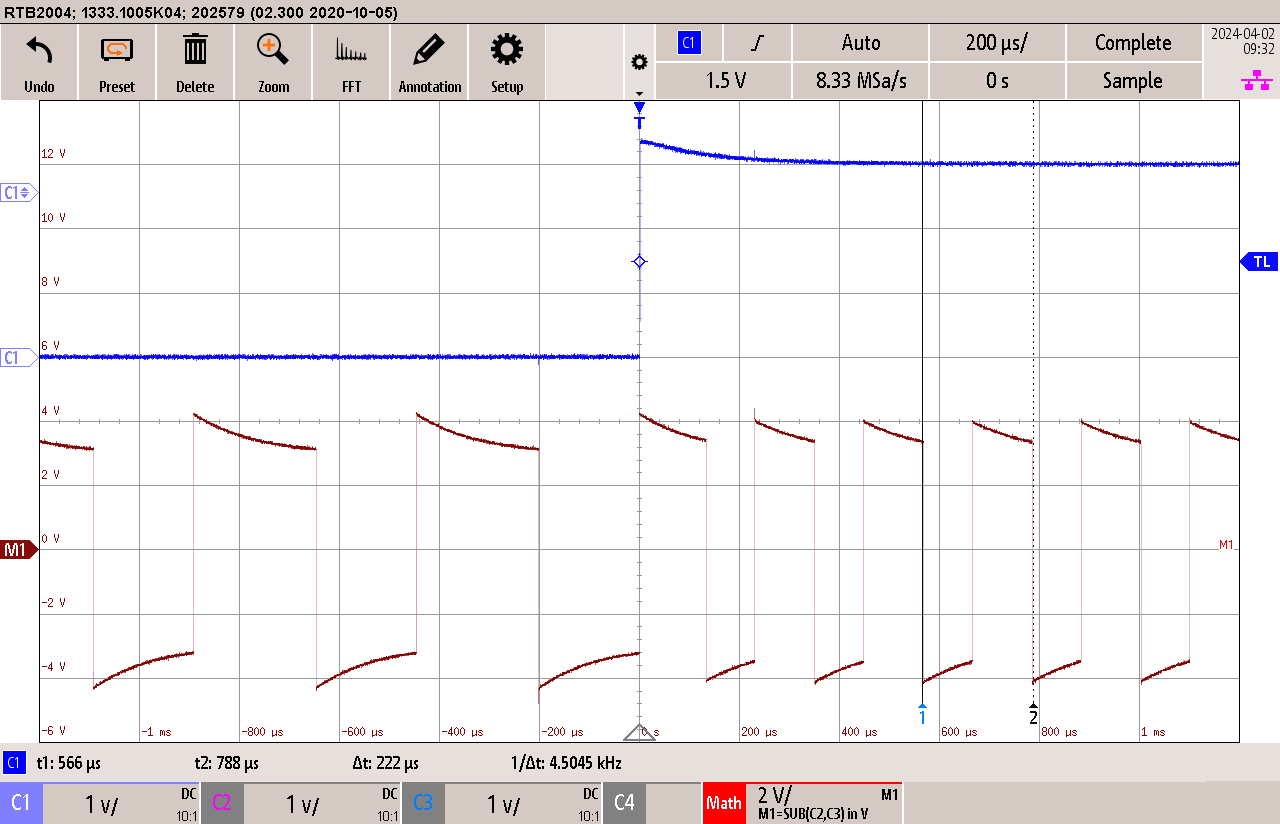
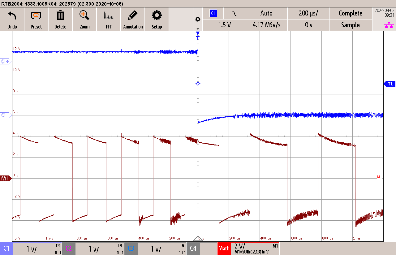
The buzzer’s tone switching, compared between LTspice and the same point measured on the real circuit, confirmed the design worked on real hardware, not just on paper:
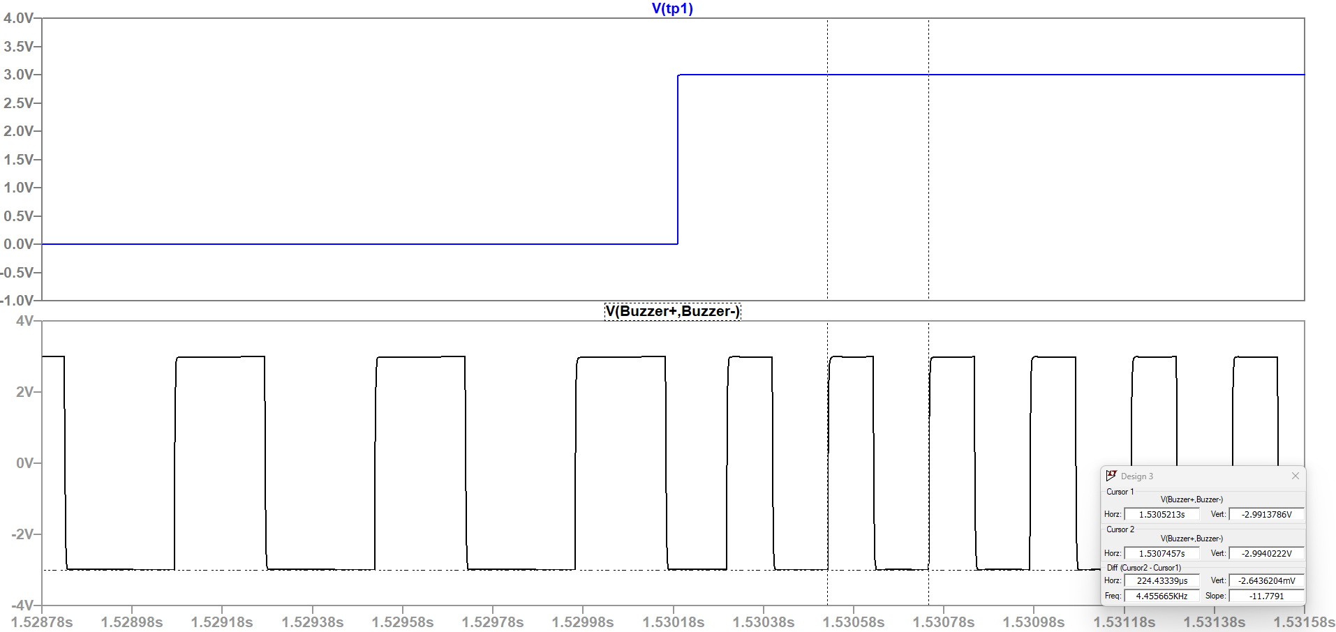
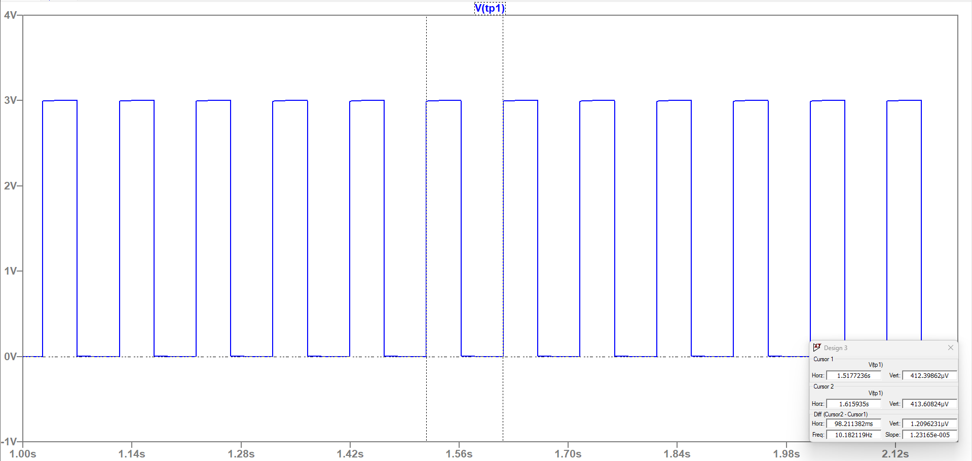
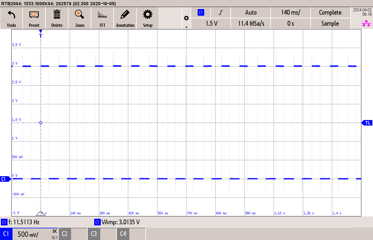
The control oscillator’s frequency matched too:
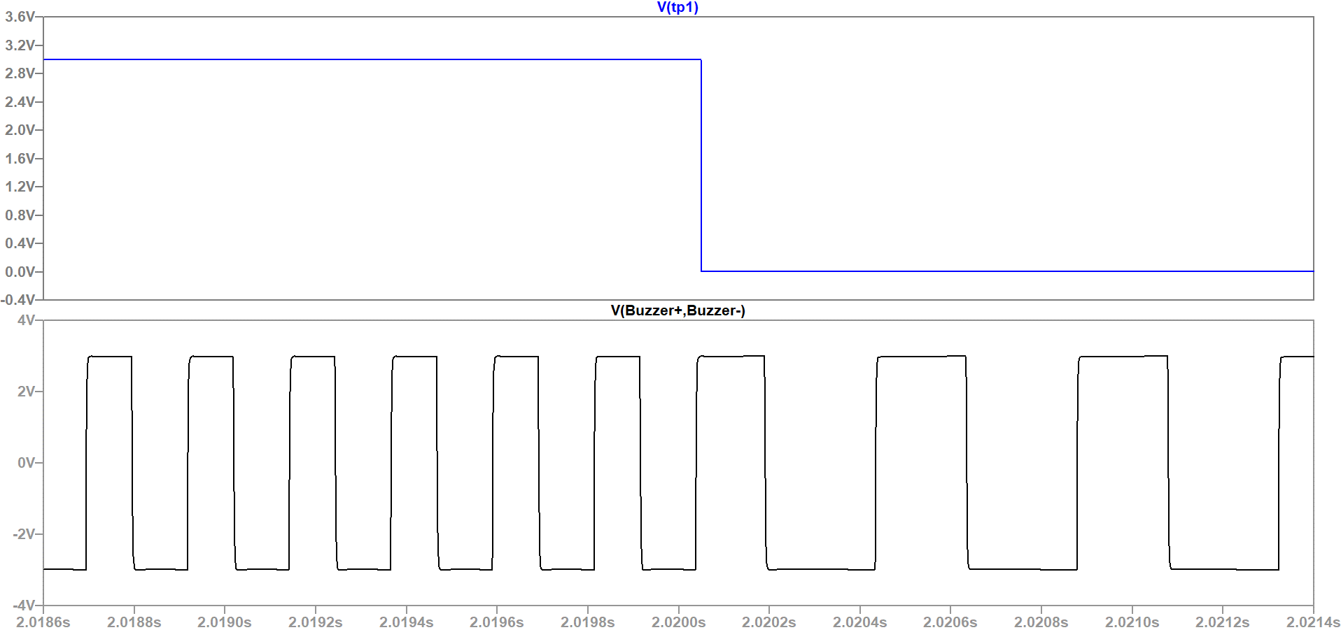
As did the falling-edge transition that triggers a tone change:
Current status
Completed: simulated and measured results matched closely across every check, on real hardware. This was a closed university assessment; no further development is planned.
What I learned or am proud of
The datasheet’s oscillator constant not quite holding at this circuit’s actual 3V supply is a small but real example of a bigger habit: a datasheet equation is a model with its own assumptions baked in, not ground truth, and it’s worth checking against simulation and a real bench measurement before trusting it at the edge of its assumed conditions.